|
Micro/Mini Pop Box Build Instructions Materials:· Enclosure back panel · 12-inch din rail · #8 ½-inch and #8 1-inch self-drilling screws · Washers to fit screws · Two APC-DIN-SS enclosures with 4 GIGEAPC-HV surge suppressors installed in each · Two din-rail endcaps · Power supply: o For Micro: SDR-240-48 o For Mini: SDR-480-48 · One AC Breaker – 5A or better · Two DC Breakers o Micro: 8A and 10A o Mini: 10A and 15A · 6-position grounding bar Tools:· Drill with driver bit for self-drilling screws · Long flat-head screwdriver for manipulating DIN rail clips · Tape measure or ruler · Phillips screwdriver |
|
|
|
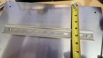
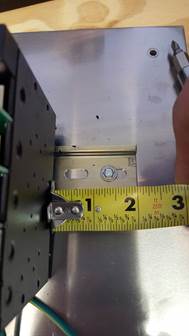
Step 1: Install the DIN rail 4 inches from the top. Use ½” #8 self-tapping / drilling screws. Be sure to put the left screw at least 2 inches from the edge (the picture is not correct). |
|
|
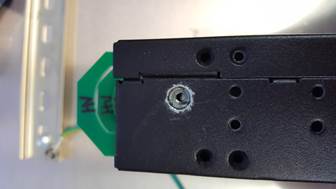
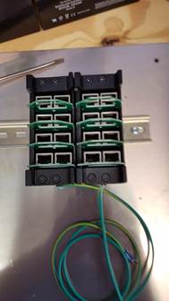
Step 2: Remove the grounding wire from the back of the DIN rail mount surge suppression enclosure. Do not throw the wire away. |
|
|
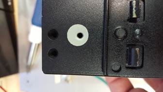
Step 3: Remove the screw from the bottom of the enclosure and scratch the paint off around the screw hole. This will be a new grounding point, so we want plenty of contact between the raw metal and the wire connector. |
|
|
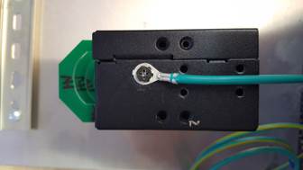
Step 4: Screw the grounding wire into the bottom of the enclosure. Point the wire toward the back of the enclosure. |
|
|
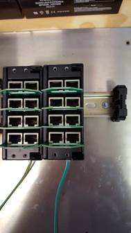
Step 5: Attach the enclosure the DIN rail 2 inches from the edge. |
|
|
Step 6: Repeat steps 2-4 with the second enclosure. Install it to the left of the first. |
|
|
Step 7: Install the DIN rail end bracket to the end of the right side of the DIN rail. |
|
|
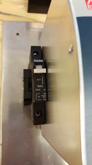
Step 8: Install another DIN rail end bracket on the left side, then install the AC breaker (5A or larger) followed by the power supply on next to the left bracket. |
|
|
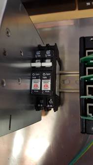
Step 9: Install two DC breakers immediate right of the power supply. For the Micro: 10A on the left, 8A on the right. For the Mini: 15A on the left, 10A on the right. |
|
|
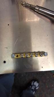
Step 10: Remove the left and right screws from the grounding bar. Install the bar near the bottom right of the panel, as shown using 1-inch #8 self-drilling screws. Replace the right and left grounding screws. |
|
|
Step 11: |
|
|
|
|
|
|
|
|
|
|
|
|
|
VARIATIONS: You can add larger images here. |
|
|
SUMMARY OF THE
BASIC RULES: RULE #1: RULE #2: RULE #3: RULE #4: |
|